
Features
- Reliable data acquisition via RS-485 (Modbus RTU)
- Cost-effective modules for industrial field use
- DIP switches for quick baud rate and address setup
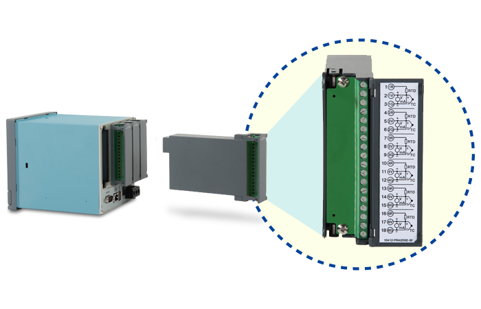
- Modular design with flexible digital/analog I/O
- Isolation protection for safe, stable field operation
- LEDs indicate power, communication, and I/O status
- Compatible with SCADA, PLC, and HMI integration
- IO Studio software for real-time setup and diagnostics
- Optional PC tool for data viewing and testing
- DIN rail mountable for easy installation
-
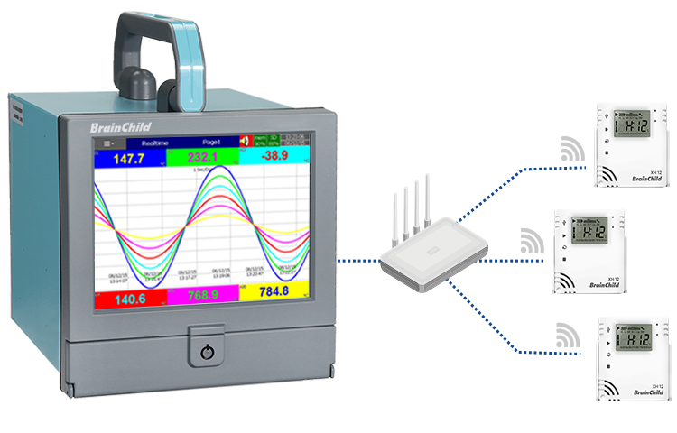
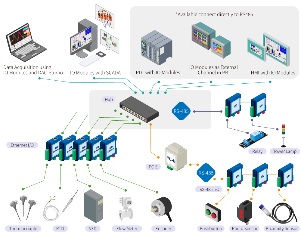
RS-485 multi-drop communication, max 32 nodes
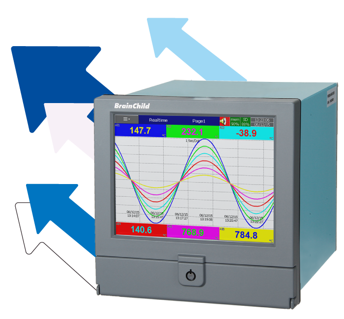
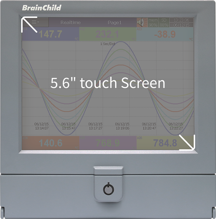
Real-Time Visibility × Effortless Configuration
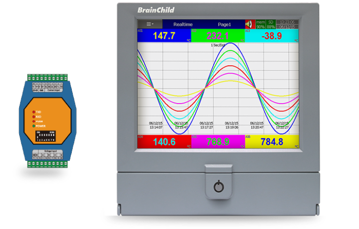
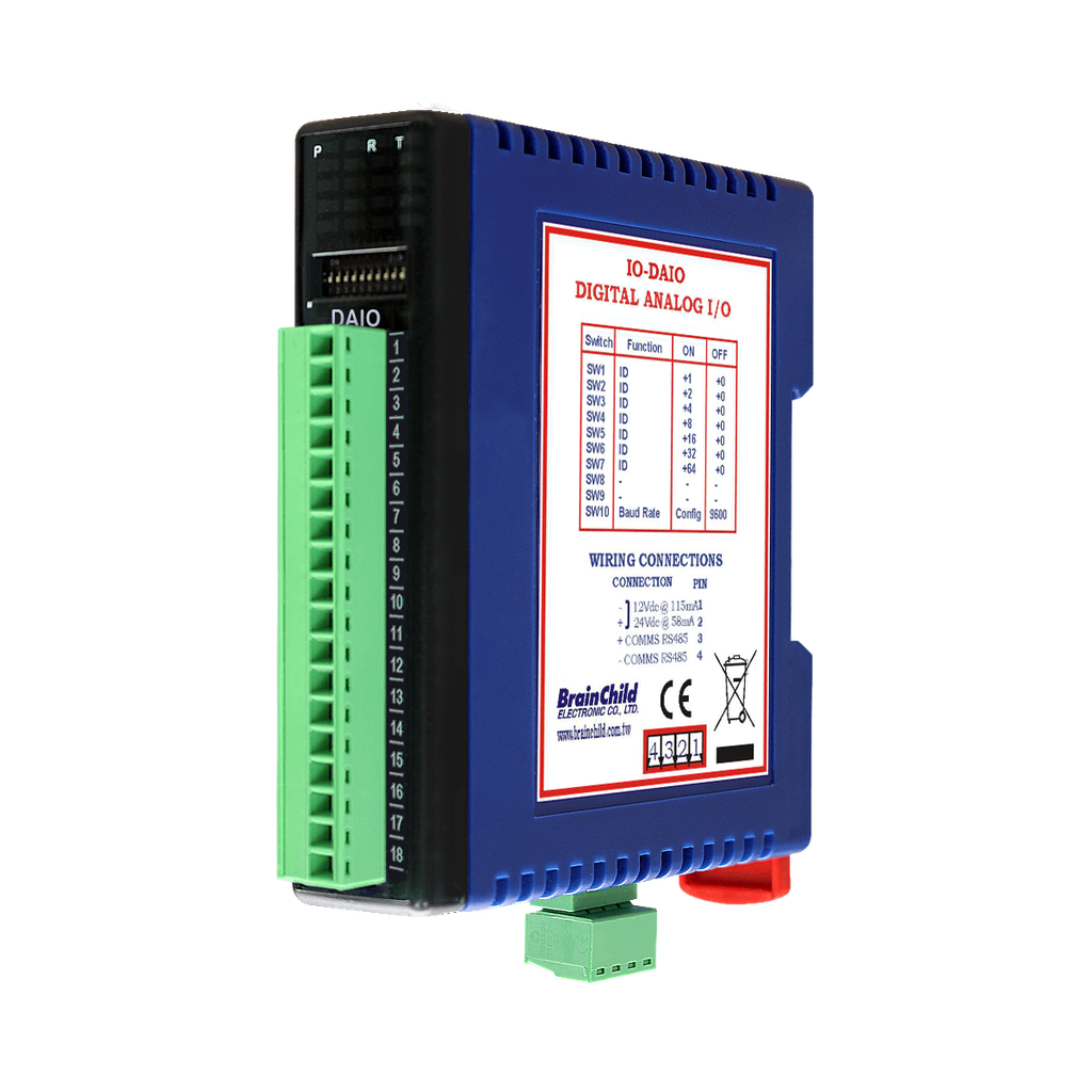
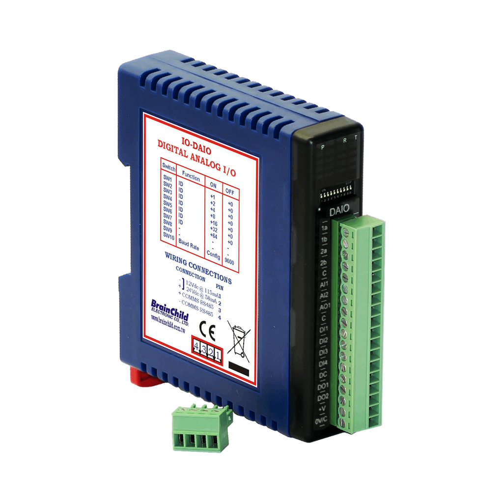
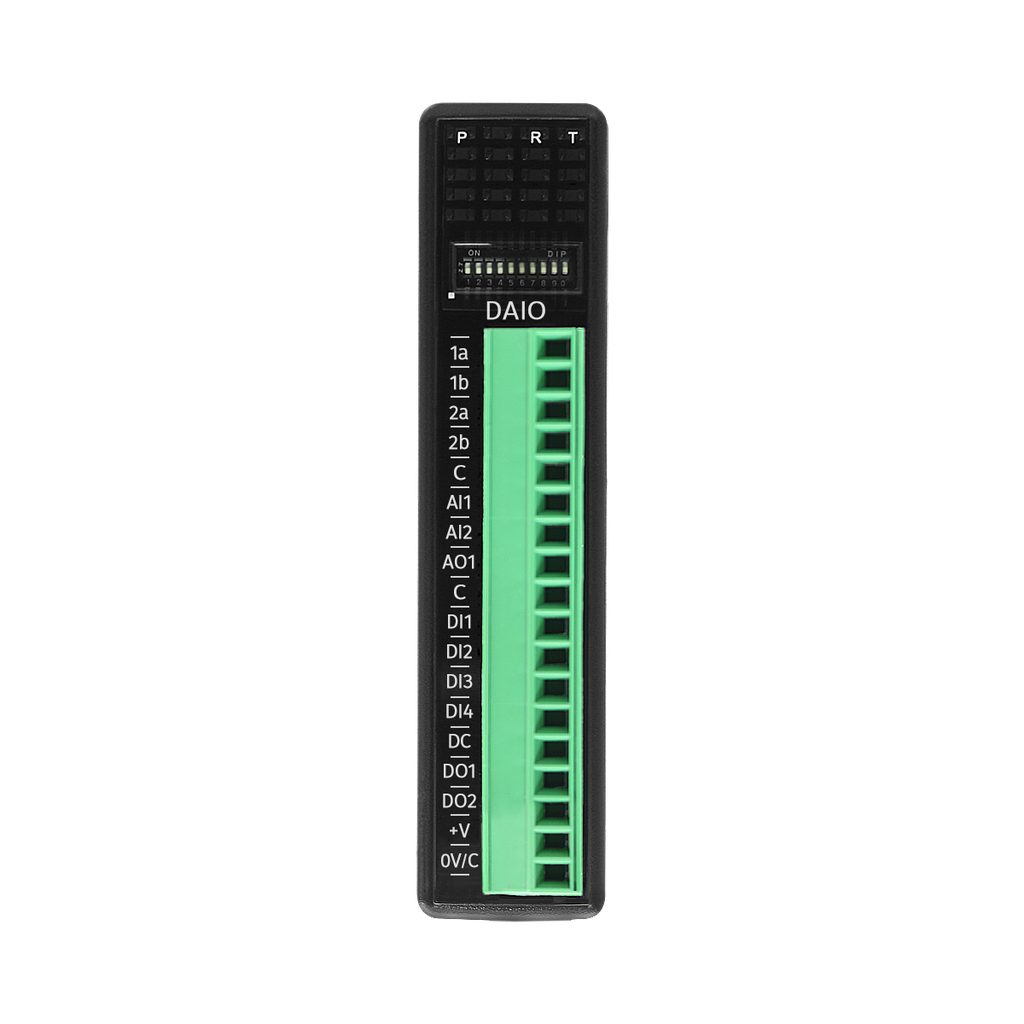
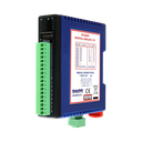
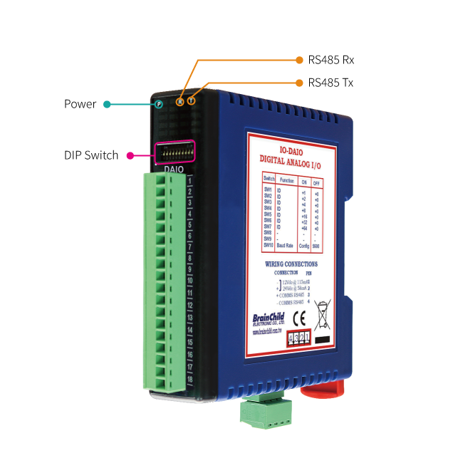
Front Panel LED Indicators & DIP Switch Setup
The IO-DAIO module is equipped with intuitive front panel LED indicators and built-in DIP switches for streamlined field operation.
The LED indicators provide real-time status feedback on power, communication, and relay output states, enabling users to verify system conditions at a glance.
DIP switches allow quick, tool-free configuration of communication parameters and node address directly on-site—simplifying setup and reducing installation time.
- Power: Flashes to indicate the CPU is running.
- RS485 Rx: Flashes to indicate the unit has received a valid Modbus message.
- RS485 Tx: Flashes to indicate the unit has sent a Modbus message.
- Dip Switch: Allows on-site configuration of address and baud rate.
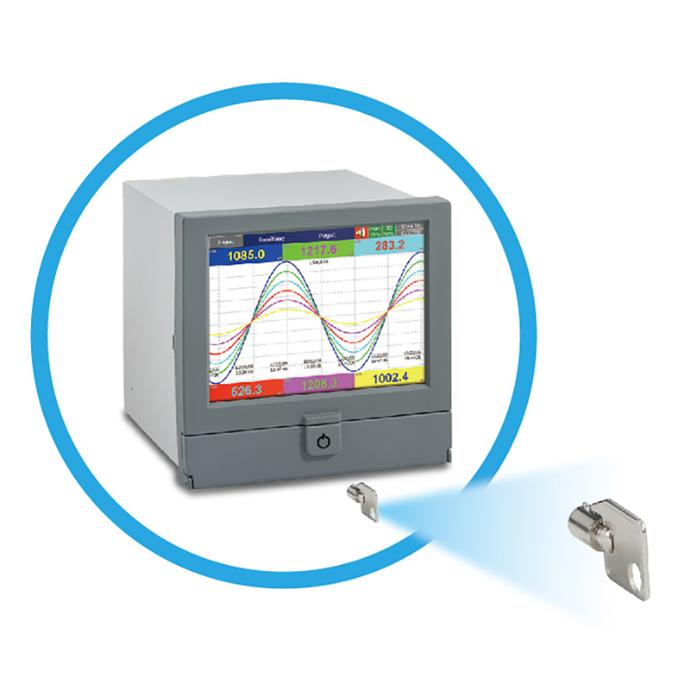
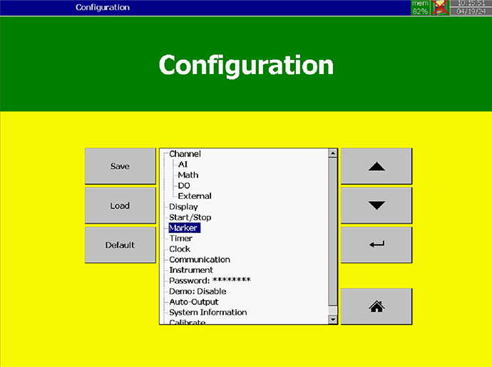
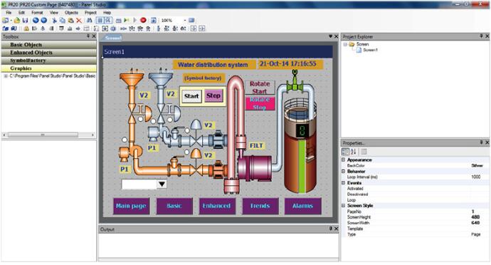
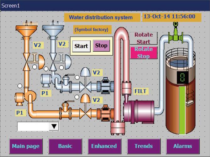
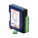
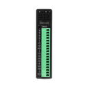
Flexible and Efficient System Configuration Solutions
Our modular industrial control products offer a simple and intuitive configuration experience, making it easy to build automation architectures tailored to your needs. Whether you're expanding I/O capacity or integrating with existing systems, we provide stable and flexible solutions to support your operations
.
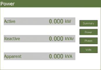
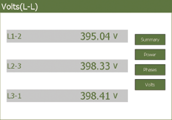
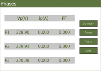
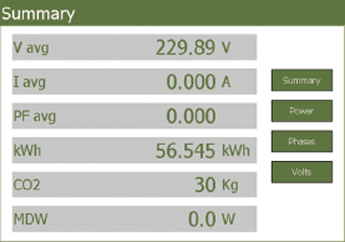
Smart Monitoring Software Suite
Comprehensive tools for real-time monitoring, historical analysis, and device configuration.
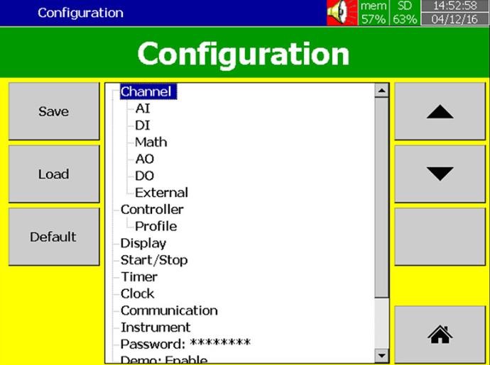
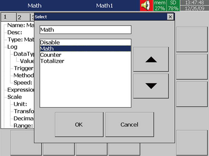
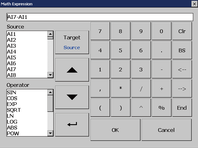
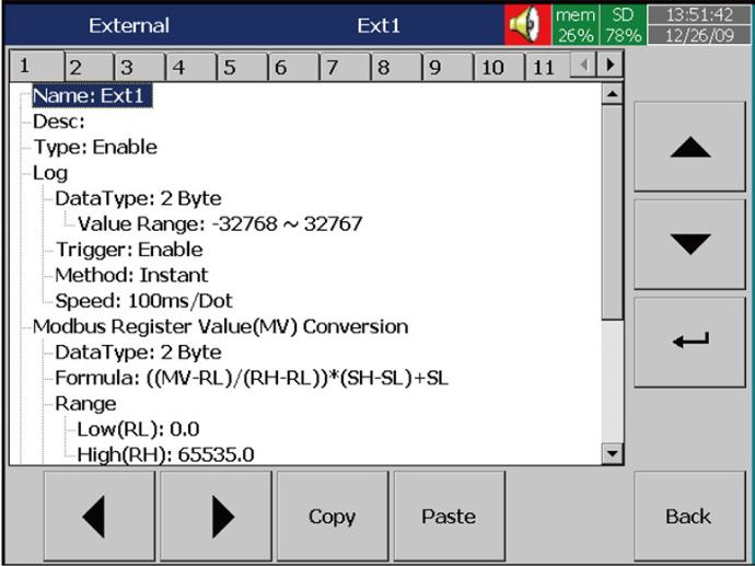
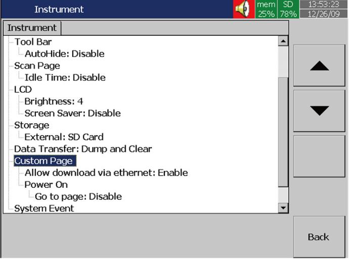
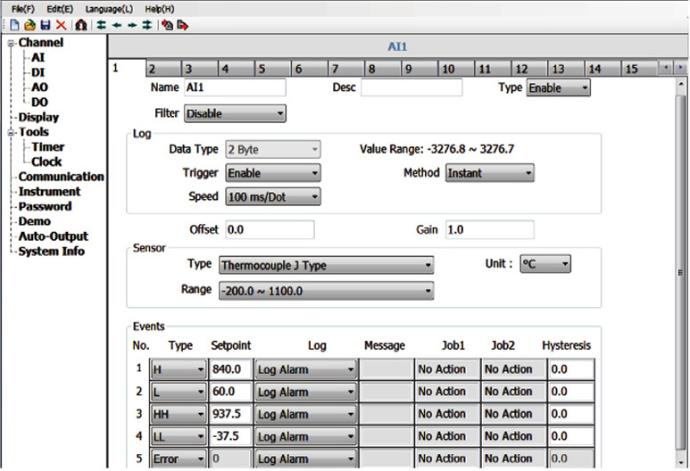
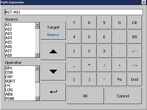
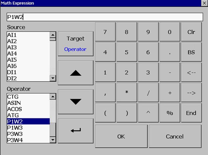
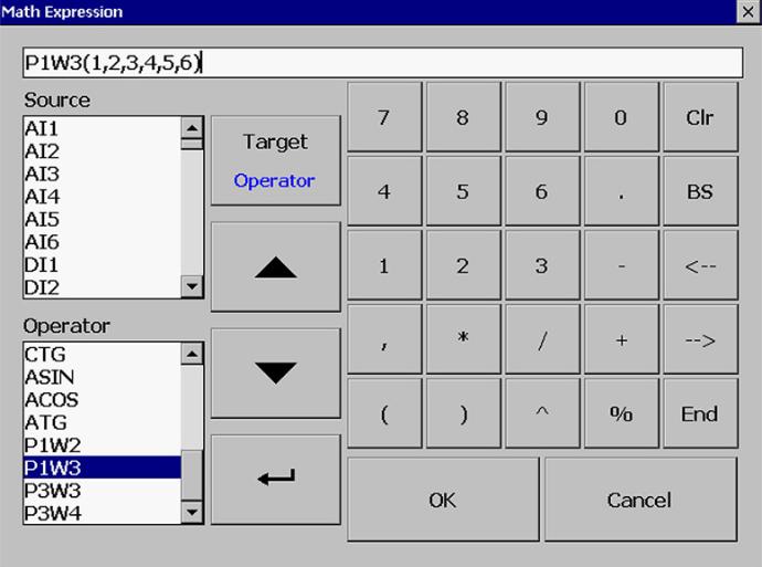
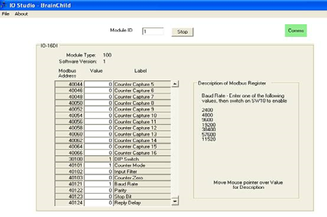
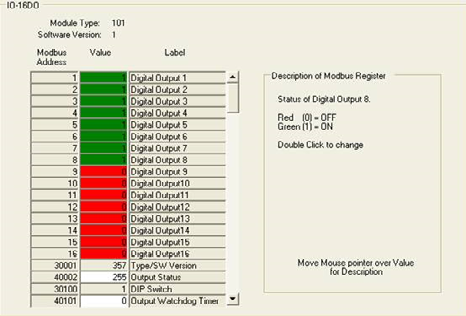
1. IO Studio
IO Studio is a Windows-based configuration software designed for setting up and troubleshooting I/O modules on the network. It allows users to connect to RS485 Modbus RTU modules via RS485 serial port, RS232 to RS485 converter, or USB to RS485 converter.
-
Real-time data monitoring and configuration
-
Easy troubleshooting interface
-
DIP switch address setting on module front panel
-
Supports Modbus RTU communication
-
User-friendly operation for quick deployment
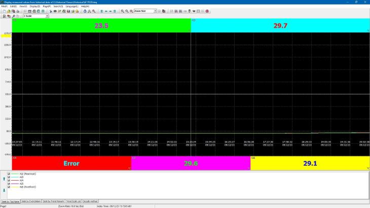
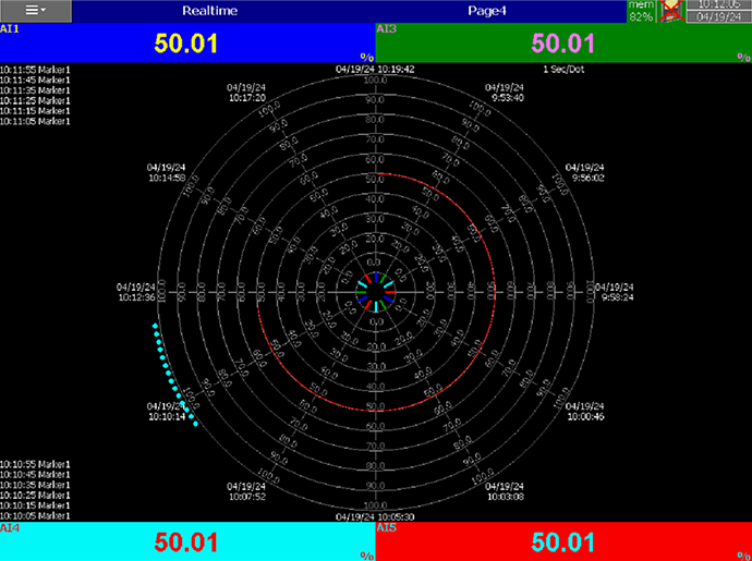
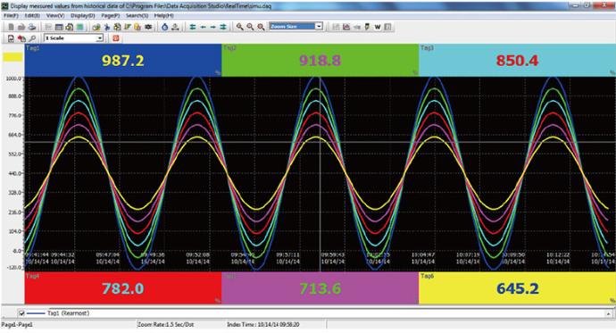
2. Historical Viewer
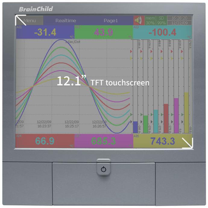
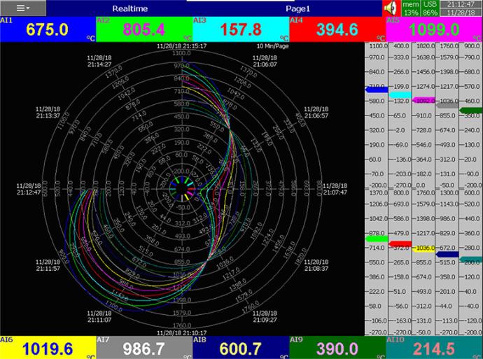
Historical Viewer provides robust tools for visualizing and analyzing historical data and alarms, making it ideal for auditing, diagnostics, and performance reporting.
Displays trends, alarms/events, and daily/weekly/monthly reports
Tabular view with comment annotations
Search by time, tag, event, or remark
Zoom and pan capabilities
Flexible time scale resolution (100 ms/dot to 1 month/page)
Export to CSV; auto-import/export features
Print trends, event logs, reports, and tag data
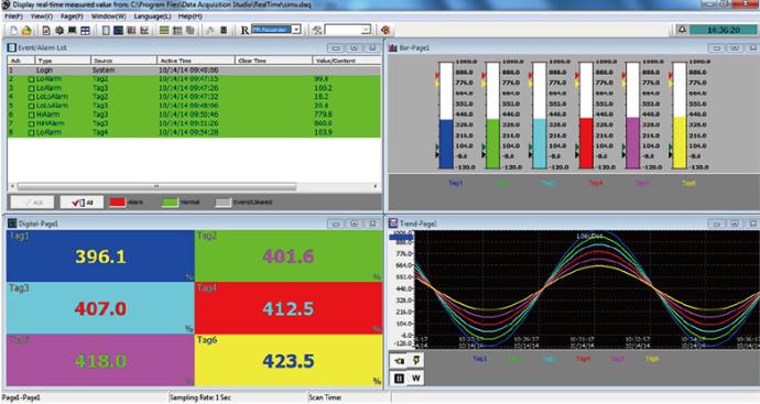
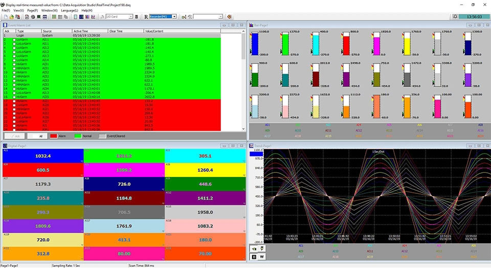
3. Data Acquisition Studio (Optional)
Data Acquisition Studio(DAQ) is an all-in-one software for acquiring and monitoring data from recorders, temperature controllers, I/O modules, HMIs, and third-party devices using Modbus protocol.
- PC-based real-time monitoring and logging
- Centralized data acquisition across devices
- Intuitive interface with easy setup
- Compatible with wide range of industrial devices
Applications


Specification
General Specifications
Connectors
Approval Standard
Combination Module
Download
 IO Modules_EN
 Modbus IO Modules_EN
 IO Studio_V2.8
 Data Acquisition Studio_V2.51(2312) for PR1.42 (2312) or earlier
Visit Download Center to See More Documents & Tools of This Product. Visit