Features
- 18-bit A/D conversion for high accuracy
- 3A relay output for direct load switching
- Supports TC, RTD, mV, VDC, and mA inputs
- Multiple alarm modes: normal or latching
- User-configurable via keypad or PC software
- Offset and digital filtering for stable reading
- Event input for remote control functions
- RS-232 / RS-485 communication available
- Analog retransmission (mA or VDC) optional
- Standard 1/4 DIN size for panel mount
- IP65-rated front panel option (with rubber seal)
- Dual display for PV and SP visibility
- Modbus RTU protocol supported
- Built-in cold junction compensation
- Compliant with CE, UL, FM standards
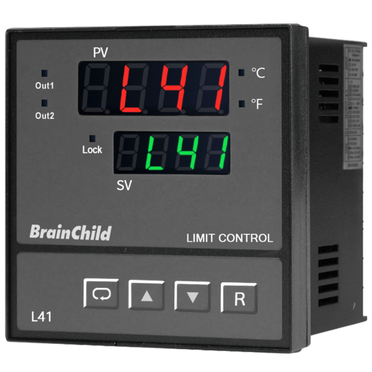
L41 Delivers Reliable Overheat Protection
Engineered for safety-critical and high-speed processes
The L41 limit controller from Brainchild is purpose-built to protect equipment and processes from overtemperature conditions in safety-critical environments. With universal sensor input, fast 5Hz sampling, and latching safety output, L41 ensures immediate and reliable shutdown when thresholds are exceeded.
Designed with flexibility in mind, L41 offers dual display, event input for remote reset/lock, RS-232/RS-485 communication, and optional analog retransmission. Its robust design makes it ideal for use in heat treatment systems, industrial furnaces, and other fast-response process applications.
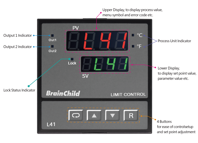
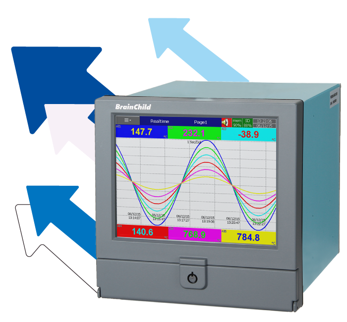
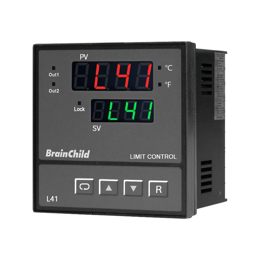
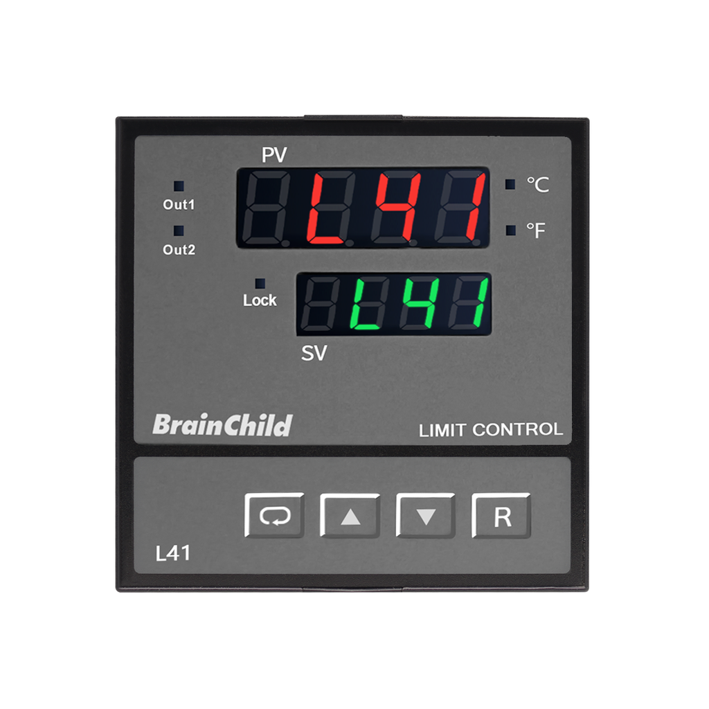
Clear Dual Display and Intuitive Interface
Simplify setup with status lights and 4-button control
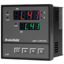
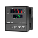
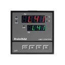
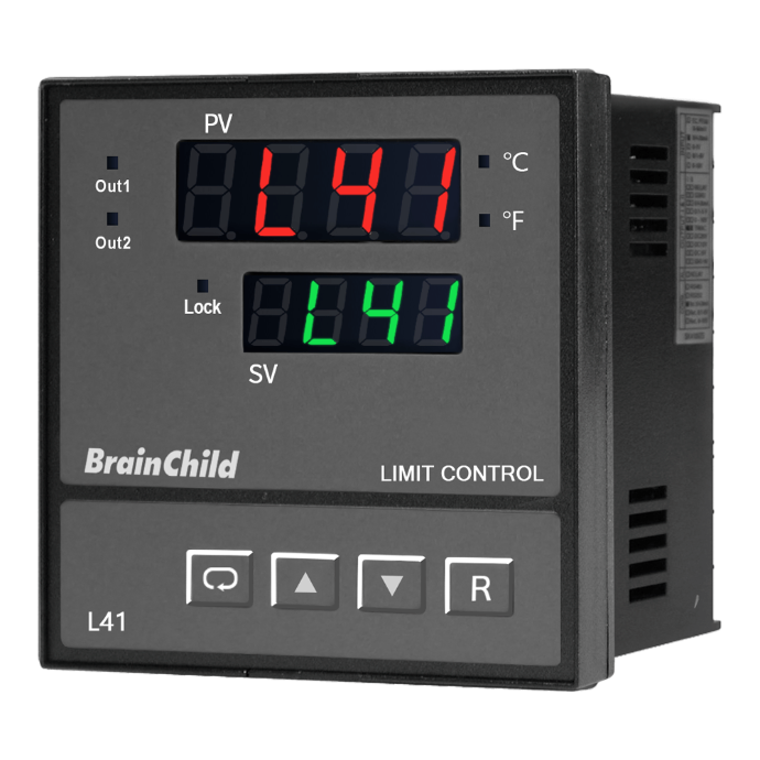
The L41 Limit Controller is equipped with a dual-line LED display that separates real-time process values and user-defined settings. The upper display clearly shows the process variable, error codes, and menu indicators, while the lower display presents setpoint values and configuration parameters.
Four tactile control buttons enable quick access to configuration menus and setpoint adjustments without complex navigation. Dedicated indicators show the status of Output 1 and Output 2, along with unit display (°C/°F) and lock status. This simplifies control and improves operational clarity, especially in high-reliability industrial environments.
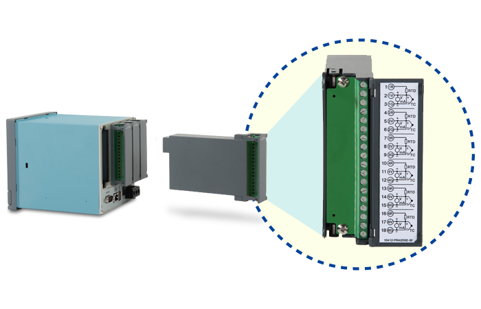
Universal Input for Accurate Detection
Supports TC, RTD, mV, voltage and current types
The L41 over-temperature protection controller features a universal input design that supports a wide range of sensor types used in industrial applications. It accepts standard thermocouples (J, K, T, E, B, R, S, N, L, C, P), PT100 RTD sensors, and analog signals including 0–60mV, 0–1V, 0–10V, 4–20mA, and more. With 18-bit A/D conversion and fast 5Hz sampling rate, it delivers stable and accurate process value readings. This input flexibility makes it ideal for integration into diverse systems requiring high-precision monitoring of temperature, pressure, or other process variables.
Flexible Output for Safety Control
Relay, SSR, Triac, retransmission and more
The L41 controller offers two independent outputs designed for flexible control and alarm functions. Output 1 is dedicated to over-limit protection and supports relay, SSR drive, or Triac output types. Output 2 can be configured for various purposes including alarm signaling, analog retransmission (4–20mA / 0–10V), RS-485 communication, or DC power output (5V / 12V / 20V). These outputs support latching mode, high/low/deviation alarms, and provide LED status indicators for easy monitoring. The versatile output design allows for seamless integration with control panels, safety interlocks, and external monitoring devices.
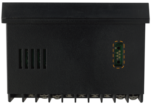
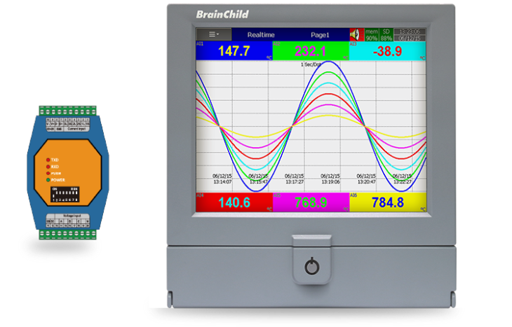
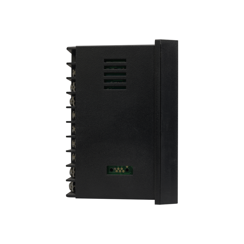
Programming Port for Automation
Enable fast setup, batch programming, and ATE test
The rear programming port of the L41 controller not only supports PC-based parameter setup via a dedicated cable, but also enables advanced manufacturing integration. It can be connected to the SNA12A for automatic programming, and to ATE systems for automated testing and calibration. This makes it a powerful tool for OEM production lines and quality control workflows.
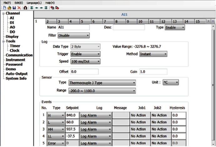
BC-SET Pro Configuration Software
Easy parameter setup, backup and firmware upgrade
BC-SET Pro is the official configuration software developed by BrainChild for its over-temperature protection controllers. With a streamlined and intuitive interface, the software allows users to connect via USB programming cable and quickly configure control parameters. It supports efficient parameter editing, setting duplication between devices, and firmware upgrades to maintain device performance and stability. BC-SET Pro also enables offline configuration with the ability to save and manage multiple profiles, making it ideal for production environments, system deployment, and ongoing maintenance. Whether for new setup or existing system adjustment, this tool helps engineers and technicians simplify workflow, reduce setup time, and ensure consistent configuration across all devices.
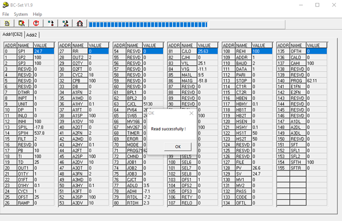
Batch Read/Write for Multiple Controllers
BC-SET allows users to connect multiple controllers of the same model and perform batch parameter read/write by defining a node address range. This feature significantly streamlines configuration in OEM or multi-device environments.
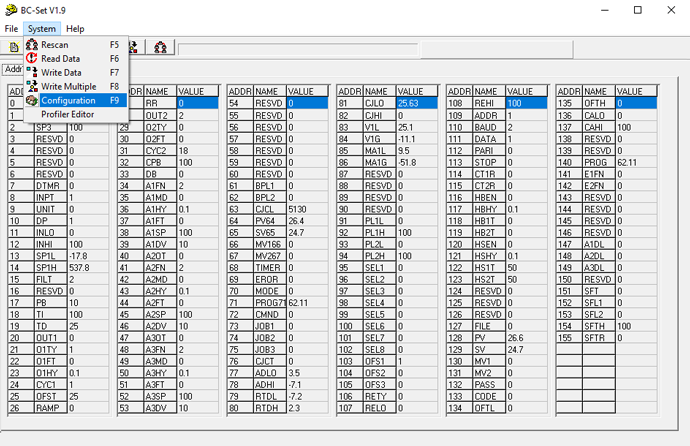
Clear and Accessible System Menu
The system menu offers quick access to key operations like Rescan (F5), Read Data (F6), Write Data (F7), Write Multiple (F8), and Communication Settings (F9). Built-in hotkeys support fast, efficient navigation.
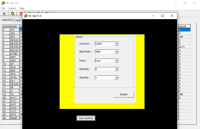
Intuitive Communication Setup Interface
The communication settings window lets users define COM port, baud rate, parity, data bits, and stop bits — with a “Default” button for quick reset and “Save and Exit” to finalize setup. Designed to reduce setup errors.
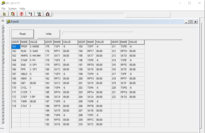
Visual Profile Editor for Programmable Controllers
For controllers with profile functionality, BC-SET provides a graphical editor to configure temperature ramp/soak segments. Users can easily read, modify, and write profile parameters for precise thermal process control.
Applications


Specification
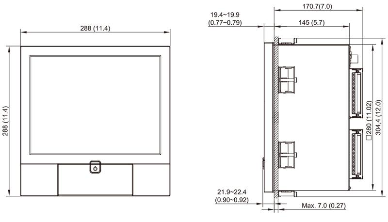
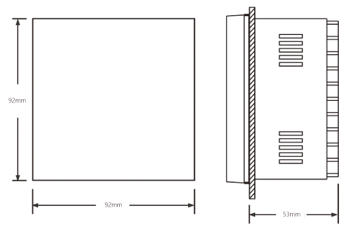
Mounting Diagram
Power
Signal Input
Output 1 / Output 2
Transmitter Power Supply (Output 2)
Digital Filter
Event Input
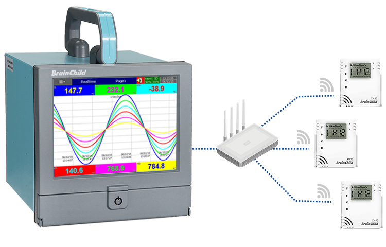
Data Communication
Analog Retransmission
User Interface
Environmental and Physical Specifications
Approval Standards
Download
 L41 & L91_EN
 BC-Set_2.0
 BC-Set Pro_V1.1.0.12(above V15)
 Data Acquisition Studio_V3.00(2603)*1-hour trial only
 Data Acquisition Studio_V2.51(2312) for V1.42 (2312) or earlier *1-hour trial only
 Demo Data Acquistion Studio


Visit Download Center to See More Documents & Tools of This Product. Visit
FAQ
The L41 is designed to monitor process values such as temperature, and trigger output actions when a user-defined limit is exceeded. It is widely used in applications requiring overheat protection, safety interlock, or critical shutdown control.
L41 supports thermocouples (J, K, T, E, B, R, S, N, L, C, P), PT100 RTDs (DIN and JIS), and analog signals such as 0–60mV, 0–10V, or 4–20mA. This universal input design allows integration into various process environments.
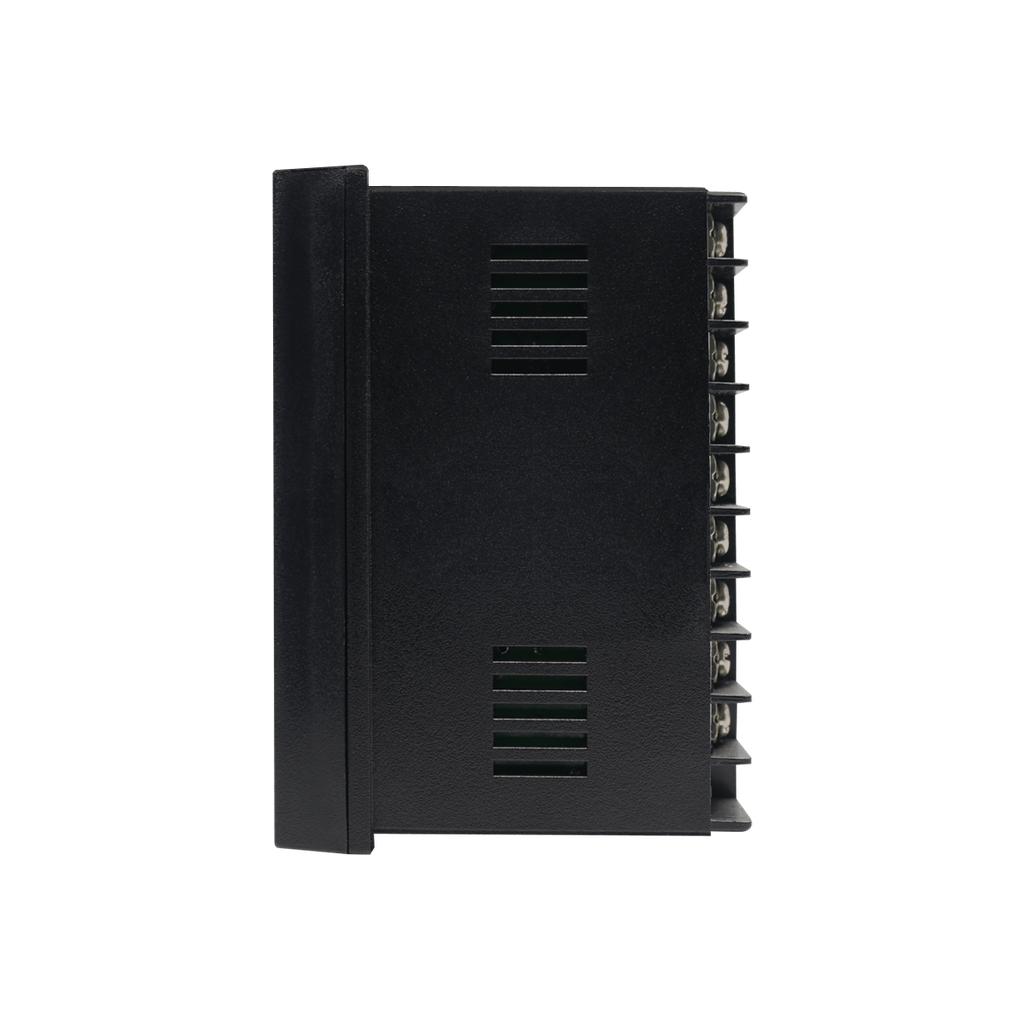
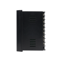
The L41 over-temperature protection controller is designed for panel mounting with a standard DIN 1/4 cutout. The required panel cutout size is 92 × 92 mm. The unit is secured using rear mounting brackets and requires a minimum panel depth of 53 mm for proper installation. This compact format allows easy integration into control panels, cabinets, or safety systems in industrial environments.
L41 provides two output channels. Output 1 supports relay, SSR, or Triac types for limit control. Output 2 is configurable for alarm output, analog retransmission, RS-485 communication, or DC power.
Yes. The L41 offers digital event input for remote reset and lockout control. This allows external push buttons or interlock systems to safely manage alarm and output states.