Features
- 1/16 DIN compact panel mounting
- 4-digit LED display with status icons
- Output indicators (OP1, OP2), °C/°F display
- Scroll / Up / Down / Reset key interface
- Manual reset and remote reset support
- Lockout function for secure operation
- Alarm annunciator and event input available
- Output 2 supports alarm, RS-485, power, retransmit
- Sampling rate: 5 times per second
- 18-bit A/D resolution for high precision
- PV shift and digital filtering function
- Optional DC power supply for sensors
- Firmware upgrade via programming port
- CE, UL61010, and EN61326 certified
- Modbus RTU protocol support via RS-485
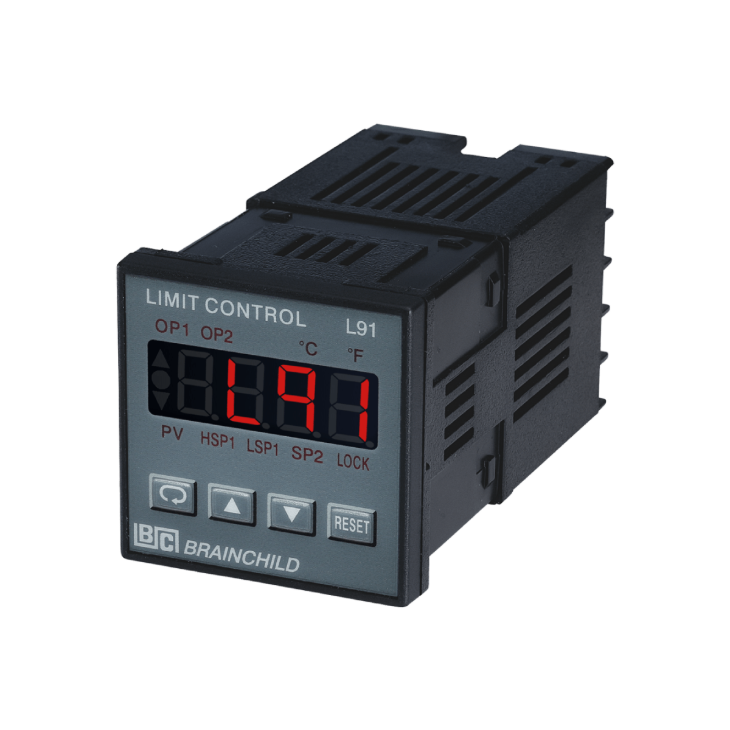
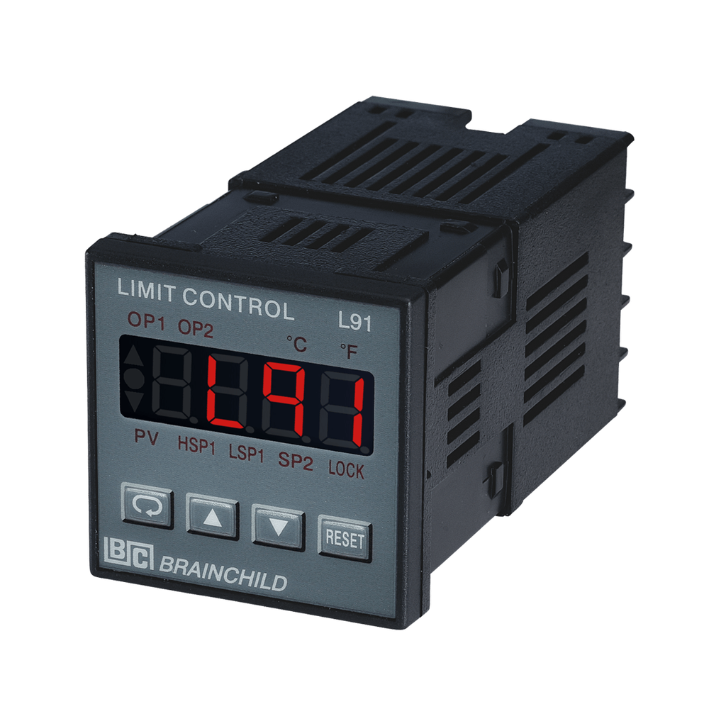
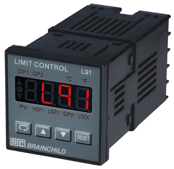
L91 Limit Controller
Compact Safety for Temperature Protection
Designed for industrial over-temperature monitoring and alarm safety
The L91 from BrainChild is a microprocessor-based limit controller engineered for precise over-temperature protection in industrial systems. With universal input compatibility (TC, RTD, voltage, current), latching relay output, and dual display interface, the L91 ensures fast and reliable safety responses. Its output flexibility includes relay, SSR, or TRIAC, while Output 2 supports expansion to alarms, Modbus communication, or analog retransmission. Users can configure the controller via front keys, RS-485, or the USB programming port using BC-SET Pro software. Certified for CE, UL, and EN standards, L91 is ideal for oven safety, thermal processing, plastic molding, or automation panels that require compact, accurate, and durable temperature control devices.
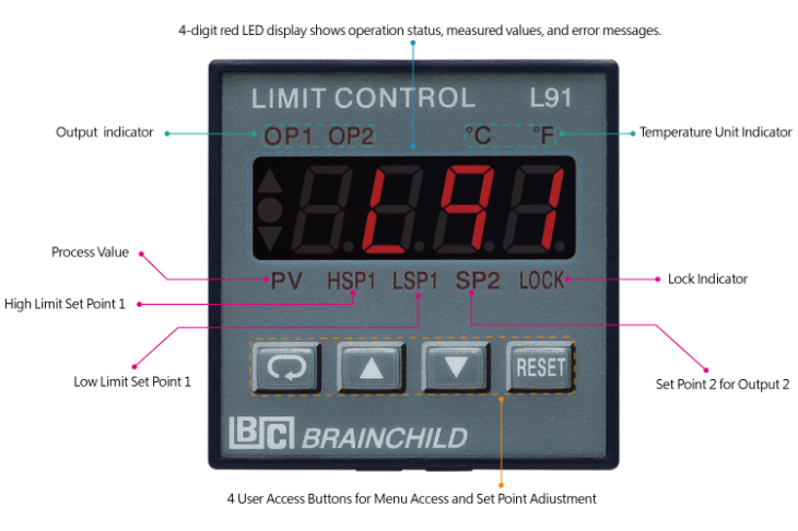
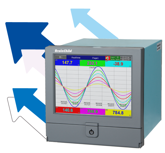
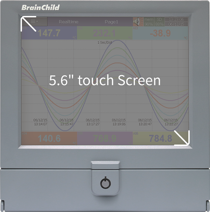
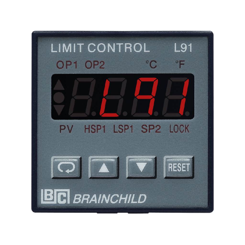
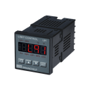
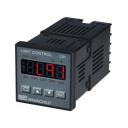
Real-Time Display with Function Keys
Monitor PV, outputs, alarms, and status at once
The L91 panel adopts a compact yet efficient layout, featuring a high-visibility 4-digit red LED display to present real-time process values (PV). Clear status indicators such as OP1 and OP2 provide immediate visual feedback for output activation, while °F and °C symbols indicate selected temperature units. Additional labels like "PV", "SP1", "SP2", "MAN", and "AT" are embedded to support operator recognition across operating or tuning states. The four-key interface includes Scroll, Up, Down, and Reset (R) buttons, allowing users to navigate menus, adjust parameters, and reset alarms efficiently. The Reset key also supports unlock/confirm actions via long press. The panel further includes a LOCK status LED, which secures access against unauthorized configuration changes. This user interface simplifies configuration and enhances operational safety in field deployment, OEM integration, or panel system control.
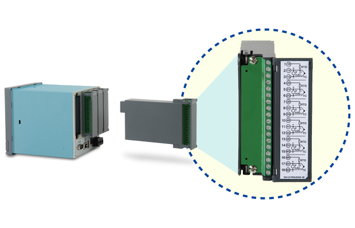
Universal Input Compatibility for Accurate Monitoring
Supports TC, RTD, Voltage, Current, and mV Signals
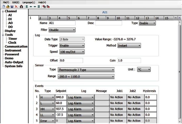
The L91 is equipped with a high-precision 18-bit A/D converter and supports a wide variety of input signals including thermocouples (J, K, T, E, B, R, S, N, L), RTDs (PT100 DIN and JIS), low voltage (mV), standard voltage (0–1V, 0–10V), and current (0–20mA). With a sampling rate of 5 times per second (200ms), it ensures rapid response and stable measurement. Adjustable parameters include decimal point location, PV offset, and display resolution. Additional protections such as sensor break detection and programmable digital filtering enhance system reliability and measurement stability.
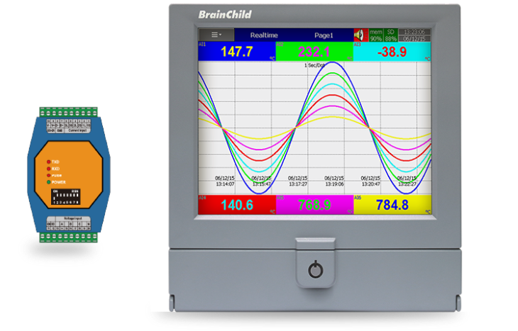
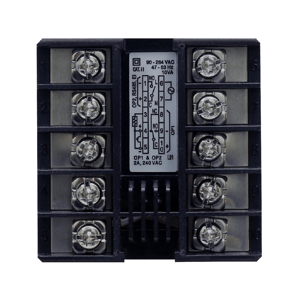
Dual Channel Outputs for Limit, Alarm, and Sign
Relay, SSR, TRIAC Outputs + Optional RS-485 or
The L91 provides two output channels—Output 1 is dedicated for primary limit control using relay (2A/240VAC), SSR drive (5V/30mA or 14V/40mA), or TRIAC (1A continuous, 20A surge). Output 2 is configurable for alarm output, RS-485/RS-232 communication, retransmission (4–20mA, 0–10V, etc.), event input, or DC power supply (5V, 12V, 20V). High/low limit control, alarm modes (normal, latching), and programmable logic enable the L91 to adapt to diverse process safety and automation scenarios
.
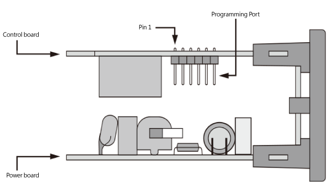
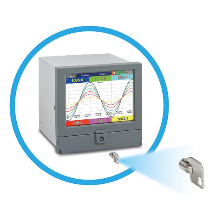
Offline Programming via Dedicated Cable
Clone settings, update firmware, calibrate via PC
The L91 features a built-in programming port designed specifically for efficient offline setup, system calibration, and maintenance operations. By using the official CC91-2 communication cable in conjunction with BrainChild’s configuration software, users can conveniently connect the device to a PC to replicate settings across multiple units, perform firmware upgrades, and carry out factory calibrations. This direct-access interface is especially beneficial in OEM, system integrator, or production line environments where uniformity and rapid deployment are essential. Unlike conventional USB ports, the programming port utilizes a proprietary connection to ensure stable, interference-free communication and avoid accidental field changes. Moreover, it operates independently of baud rate, address, or stop bit settings, allowing for plug-and-play-like functionality during initial installation phases.
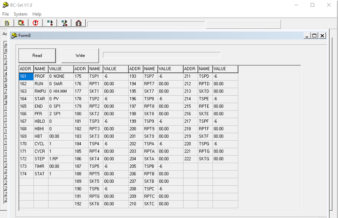
BC-SET Pro Configuration Software
Easy parameter setup and firmware upgrade for Core Series controllers
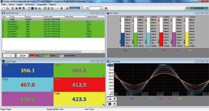
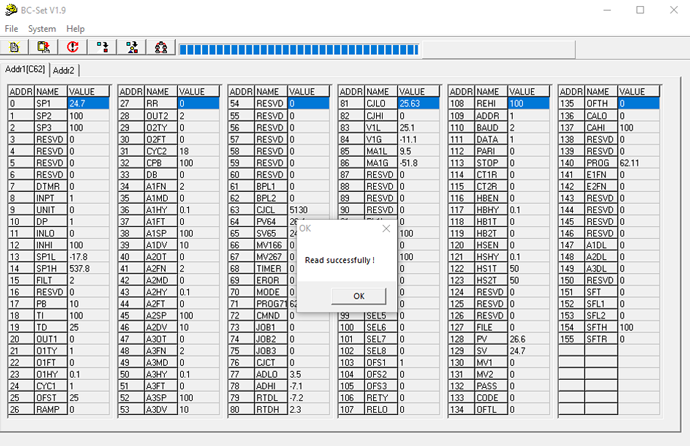
BC-SET Pro is the official configuration software for BrainChild’s Core Series temperature controllers. With a user-friendly interface, it allows engineers and technicians to configure parameters, copy settings between devices, and perform firmware upgrades via USB connection. The software supports offline setup and can store multiple configuration files, making it ideal for OEM production lines, system integrators, and field engineers.
Batch Read/Write for Multiple Controllers
BC-SET allows users to connect multiple controllers of the same model and perform batch parameter read/write by defining a node address range. This feature significantly streamlines configuration in OEM or multi-device environments.
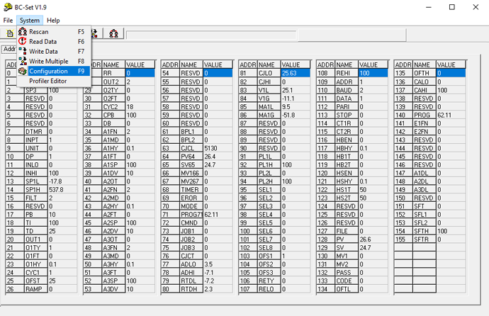
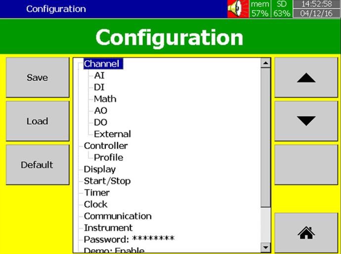
Clear and Accessible System Menu
The system menu offers quick access to key operations like Rescan (F5), Read Data (F6), Write Data (F7), Write Multiple (F8), and Communication Settings (F9). Built-in hotkeys support fast, efficient navigation.
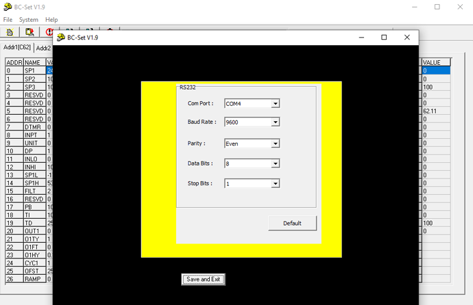
Intuitive Communication Setup Interface
The communication settings window lets users define COM port, baud rate, parity, data bits, and stop bits — with a “Default” button for quick reset and “Save and Exit” to finalize setup. Designed to reduce setup errors.
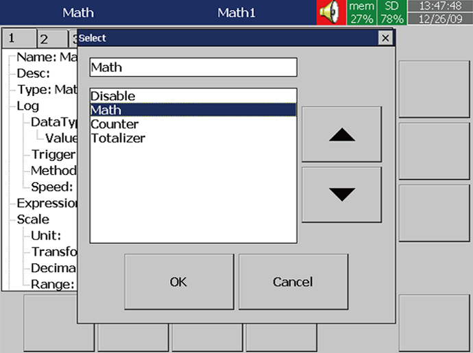
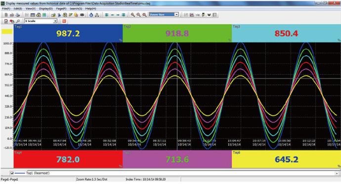
Visual Profile Editor for Programmable Controllers
For controllers with profile functionality, BC-SET provides a graphical editor to configure temperature ramp/soak segments. Users can easily read, modify, and write profile parameters for precise thermal process control.
Applications


Specification
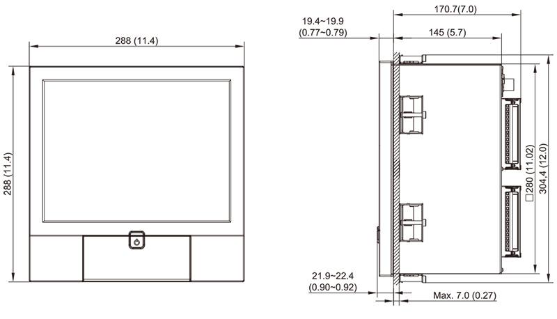
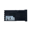
Mounting Diagram

Power
Signal Input
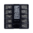
Output 1 / Output 2
Transmitter Power Supply (Output 2)
Digital Filter
Event Input
Data Communication
Analog Retransmission
User Interface
Environmental and Physical Specifications
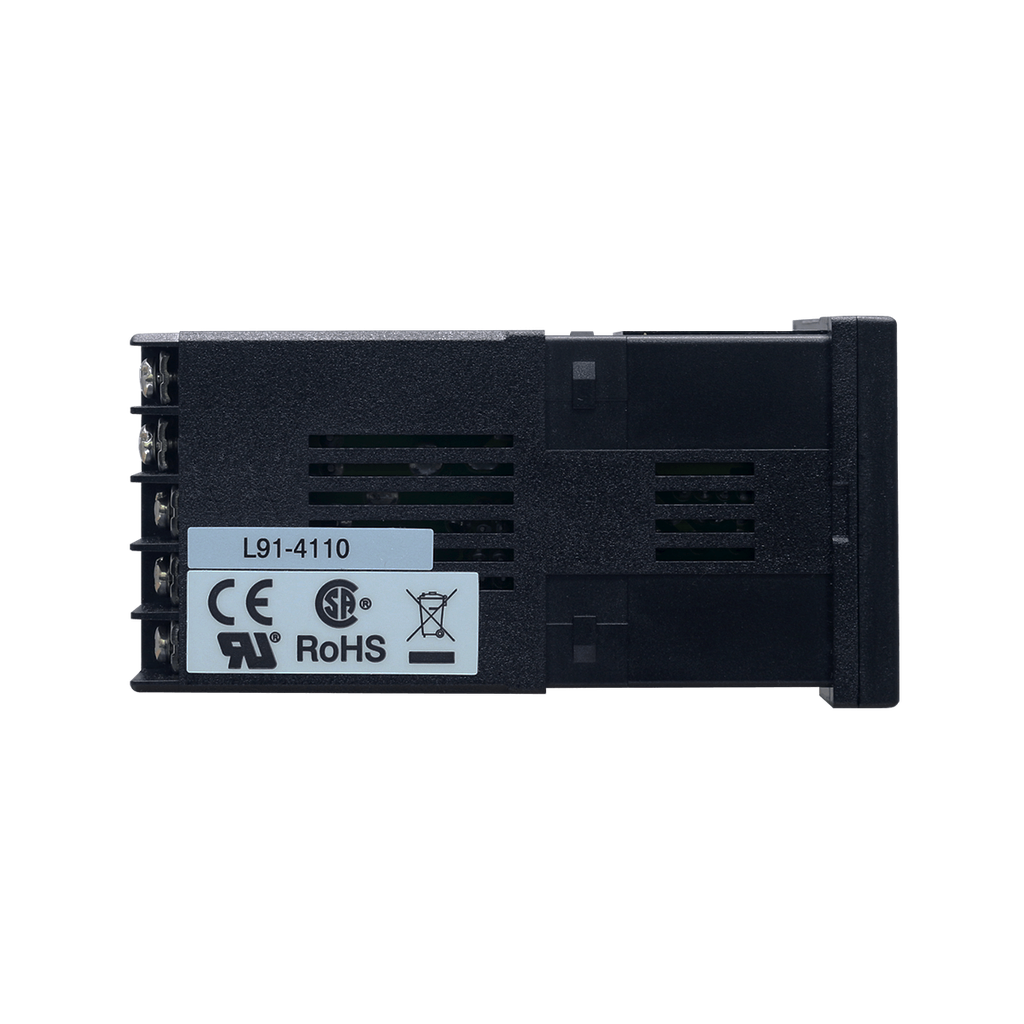
Approval Standards
Download
 L41 & L91_EN
 BC-Set_2.0
 BC-Set Pro_V1.1.0.12(above V15)
 Data Acquisition Studio_V3.00(2603)*1-hour trial only
 Data Acquisition Studio_V2.51(2312) for V1.42 (2312) or earlier *1-hour trial only
 Demo Data Acquistion Studio


Visit Download Center to See More Documents & Tools of This Product. Visit
FAQ
The L91 accepts thermocouples (J, K, T, E, B, R, S, N, L), RTD sensors (PT100 DIN/JIS), low-voltage signals (0–60mV), voltage (0–1V, 0–10V), and current (0–20mA). All input types are selectable through the panel or software. With 18-bit resolution and 5 samples/sec rate, it delivers high accuracy and fast response.
The L91 features a programming port that works with the CC91-2 communication cable and BC-Set PRO software. This allows users to clone settings, update firmware, and calibrate devices via PC, simplifying mass deployment in OEM environments.
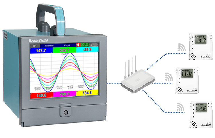
Yes, the L91 supports RS-485 via the optional CM96-1 module. It uses the Modbus RTU protocol and is compatible with SCADA systems. Once installed, users can read/write parameters and remotely configure the unit.
L91 offers high, low, deviation, and latching alarms. It also supports remote reset and lockout via digital input. Alarms can trigger relay outputs or be monitored through the panel or communication port.
The L91 is certified to UL61010, CE, RoHS, and REACH standards. The front panel is IP30-rated, and the rear terminal block is IP20 when covered. It’s designed for panel mounting in industrial control environments.