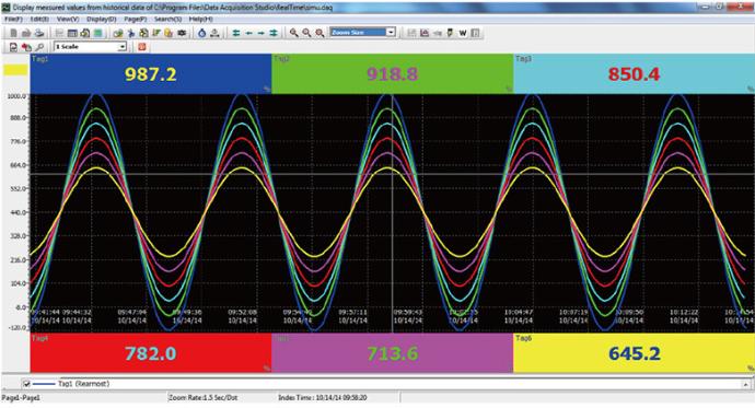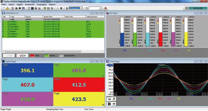
Select Series | 48mm x 48mm

L62
https://www.brainchildtw.com/web/image/product.template/59/image_1920?unique=062c7a5

Process Limit Controller

• Fast 200ms process value sampling
• Supports TC, RTD, mV, V, mA input
• Dual output: Relay or SSRD
• Optional RS-485 & retransmission
• Keypad setup with LCD display

This combination does not exist.

Features

  • Universal input with wide sensor range
  • 18-bit A/D converter ensures accuracy
  • Dual output for limit and alarm functions
  • Relay or solid-state output selectable
  • Optional analog retransmission (mA/V)
  • RS-485 Modbus RTU slave mode
  • Up to 3 alarm output configuration
  • 2 event input ports (option)
  • Programmable SEL quick menu access
  • Lockout and remote reset supported
  • 4-button keypad for intuitive control
  • LCD dual display for PV and SP values
  • LED indicators for output status
  • CE, UL, FM approved with RoHS compliance
  • Front panel IP50 protection

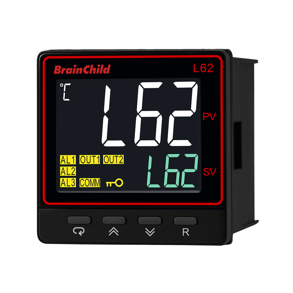
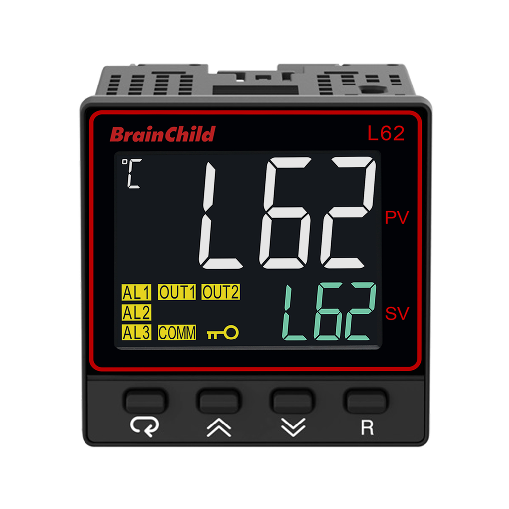
L62 Limit Controller
Safety Precision Built In

Enhancing industrial safety with advanced limit control

The L62 Limit Controller from BrainChild delivers fast, stable, and precise limit protection in space-limited industrial applications. Its compact 1/16 DIN design integrates universal sensor input, dual outputs (relay or SSR), fast 200ms sampling, and RS-485 Modbus communication for remote integration. It offers flexible alarm logic, event inputs, analog retransmission, and an optional third output channel, making it ideal for over-temperature protection in heating systems or control cabinets. With a dual-line LCD, Micro USB setup port, and BC-SET Pro support, the L62 simplifies both configuration and firmware updates. Robust front-panel operation and flexible output logic make it suitable for OEM integration or on-site safety upgrades.
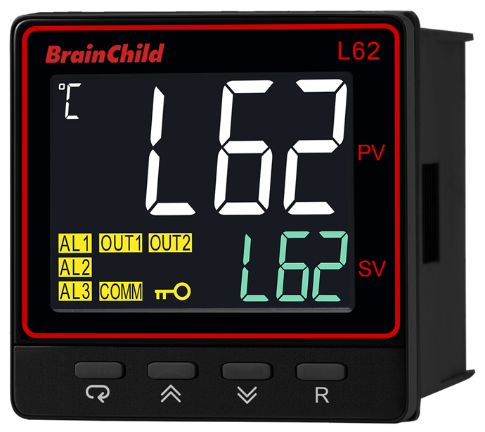
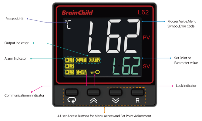
Intuitive Dual Display with 4-Key Control

Simplify setup and monitoring on-site with ease  

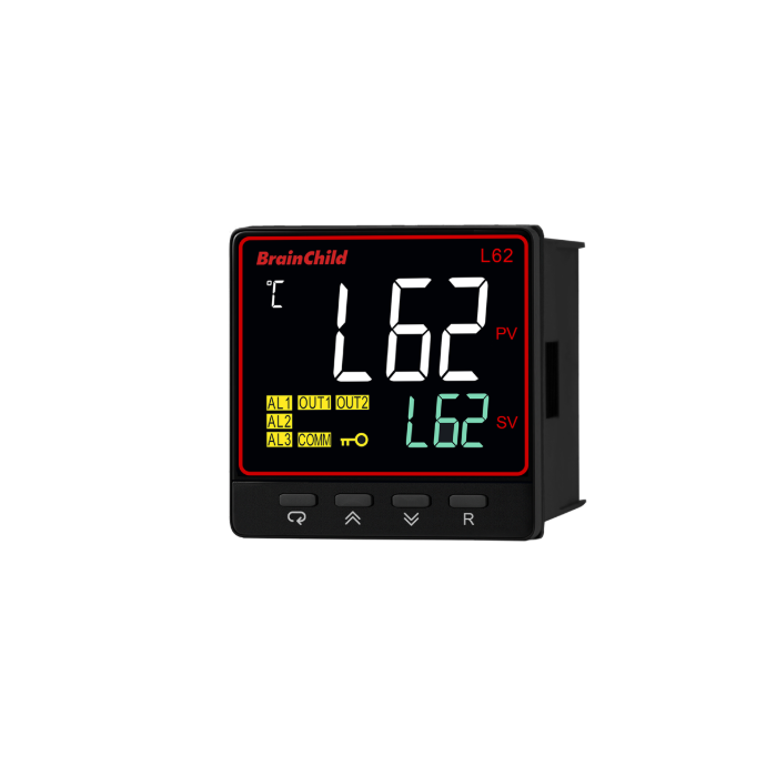
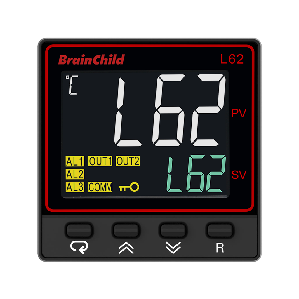
L62 features a high-visibility dual-line LCD: the upper line shows the process value (PV), unit, menu code, or error messages, while the lower line displays setpoint (SP) or parameter data. Dedicated output and lock status indicators help users instantly confirm system status. The membrane keypad includes 4 responsive buttons that enable fast access to menus, parameter editing, and alarm resets. The clean interface is optimized for OEMs and operators needing quick verification and minimal training.  

Multi-Sensor Input with High Precision

Supports TC, RTD, mV, V, and mA signals

L62 supports multiple sensor inputs including thermocouples (J, K, T, E, B, R, S, N, L, P, C), RTD (PT100 DIN/JIS), mV (0–60mV), current (0–20mA), and voltage (0–1V, 0–10V). All types are selectable via keypad or software. An integrated 18-bit A/D converter ensures fast and accurate conversion. The unit auto-compensates for sensor differences, making it suitable for heat treatment, oven, or safety-critical system monitoring.  

Dual Output with Alarm Logic Options  

Relay or SSR drive with 3rd output available

Output 1 and Output 2 can be set as relay contact (2A/240VAC) or SSR drive (5V/14V). An optional Output 3 is available for expanded alarm logic. Users can program high, low, or deviation alarms, as well as choose latching or normal reset behavior. Optional analog retransmission (4–20mA or 0–10V) provides PV feedback to recorders or PLCs. The flexible logic makes L62 suitable for shutdown, alarm, or interlock applications.  
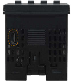
USB-Based Offline Configuration

Use BC-SET Pro software for fast setup and cloning

The L62 features a built-in Micro USB programming port on the front panel, providing engineers with a fast and convenient way to configure devices without entering menu layers manually. Using BrainChild’s BC-SET Pro software along with the CC98-1 cable and PA98-1 adapter, users can perform offline parameter setup, firmware upgrades, and device cloning with ease. This functionality is especially useful in OEM or batch deployment scenarios where consistent configuration across multiple controllers is essential. The programming port also supports ATE (Automated Test Equipment) environments, offering a standardized interface for production-line testing, calibration, or mass firmware initialization prior to delivery. Note: The port should only be used when the controller is powered and not in active process operation.  

BC-SET Pro Configuration Software

Easy parameter setup, backup and firmware upgrade  

BC-SET Pro is the official configuration software developed by BrainChild for its over-temperature protection controllers. With a streamlined and intuitive interface, the software allows users to connect via USB programming cable and quickly configure control parameters. It supports efficient parameter editing, setting duplication between devices, and firmware upgrades to maintain device performance and stability. BC-SET Pro also enables offline configuration with the ability to save and manage multiple profiles, making it ideal for production environments, system deployment, and ongoing maintenance. Whether for new setup or existing system adjustment, this tool helps engineers and technicians simplify workflow, reduce setup time, and ensure consistent configuration across all devices.
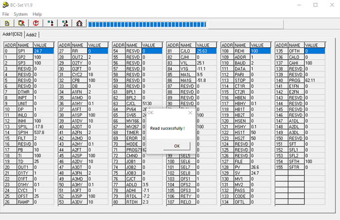
Batch Read/Write for Multiple Controllers 

BC-SET allows users to connect multiple controllers of the same model and perform batch parameter read/write by defining a node address range. This feature significantly streamlines configuration in OEM or multi-device environments.
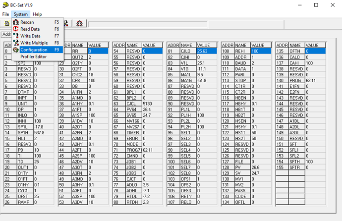
Clear and Accessible System Menu 

The system menu offers quick access to key operations like Rescan (F5), Read Data (F6), Write Data (F7), Write Multiple (F8), and Communication Settings (F9). Built-in hotkeys support fast, efficient navigation.
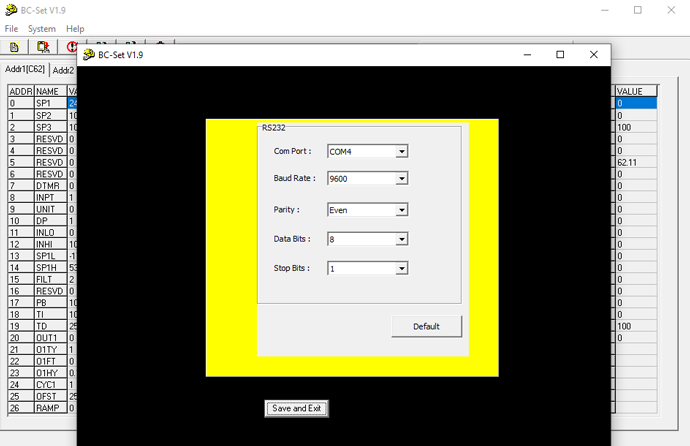
Intuitive Communication Setup Interface

The communication settings window lets users define COM port, baud rate, parity, data bits, and stop bits — with a “Default” button for quick reset and “Save and Exit” to finalize setup. Designed to reduce setup errors.
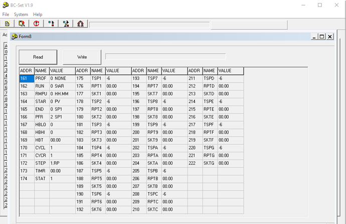
Visual Profile Editor for Programmable Controllers 

For controllers with profile functionality, BC-SET provides a graphical editor to configure temperature ramp/soak segments. Users can easily read, modify, and write profile parameters for precise thermal process control.

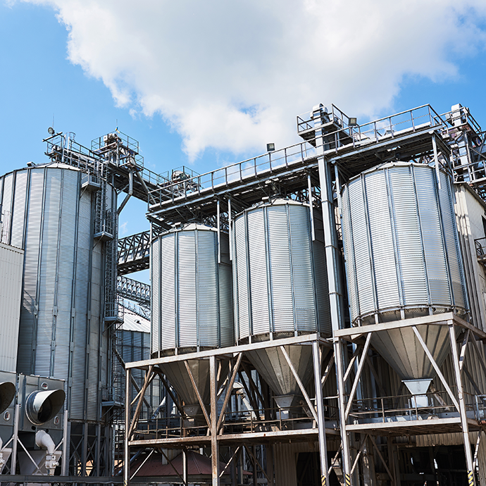
Applications
Specification

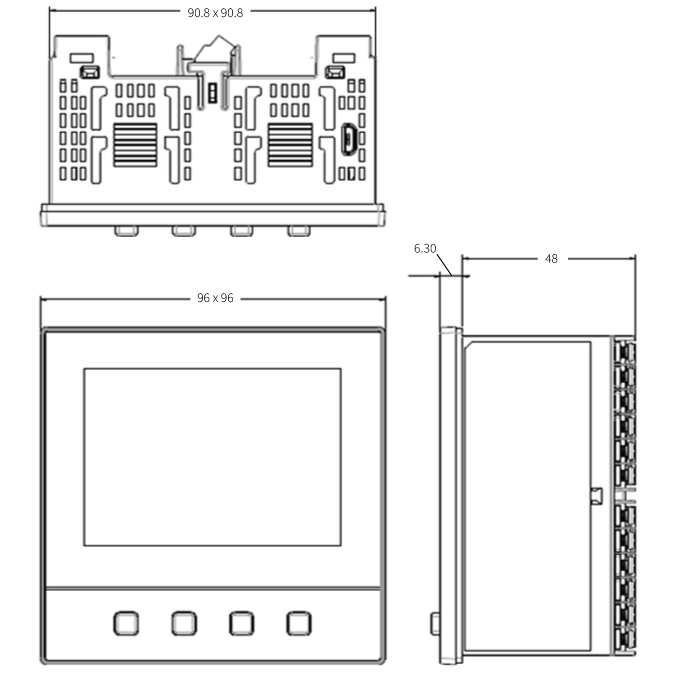
 Dimension with Clamps
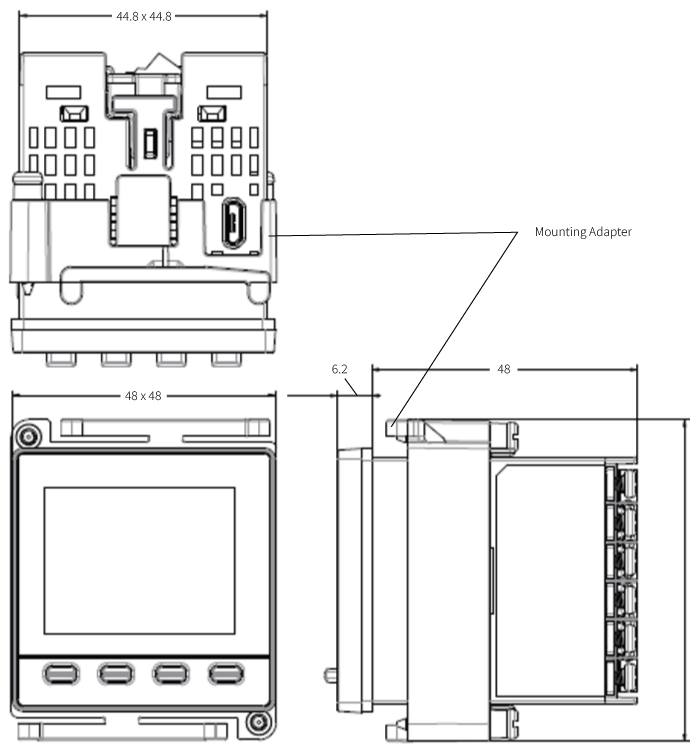

 Dimension without Clamp

 Power

Power Supply

90 ~ 250VAC, 47 ~63Hz, 20 ~ 28 VAC, 47-63Hz / 11 ~ 40 VDC

Power Consumption

10VA, 5W Maximum

Over Voltage Category

II

 Signal Input

Type

Thermocouple (J, K, T, E, B, R, S, N, L, U, P, C, D), RTD(Pt100(DIN), Pt100(JIS)), Current(mA), Voltage (V, mV)

Resolution

18 Bits

Sampling Rate

5 Times / Second (200msec)

Maximum Rating

-2VDC minimum, 12VDC maximum

Input characteristics

Type

Range

 Accuracy@ 25 °C

Input Impedance

J

-120°C ~ 1000°C D115( -184°F ~ 1832°F)

±2 °C

2.2MΩ

K

200°C ~ 1370°C (-328°F ~ 2498°F)

±2 °C

2.2MΩ

T

-250°C ~ 400°C ( -418°F ~ 752°F)

±2 °C

2.2MΩ

E

-100°C ~ 900°C ( -148°F ~ 1652°F)

±2 °C

2.2MΩ

B

0°C ~ 1820°C (32°F ~ 3308°F)

±2 °C (200°C - 1800°C)

2.2MΩ

R

0°C ~ 1767.8°C (32°F ~ 3214°F)

±2 °C

2.2MΩ

S

0°C ~ 1767.8°C (32°F ~ 3214°F)

±2 °C

2.2MΩ

N

-250°C ~ 1300°C ( -418°F ~ 2372°F)

±2 °C

2.2MΩ

L

-200°C ~ 900°C ( -328°F ~ 1652°F)

±2 °C

2.2MΩ

U

-200°C ~ 600°C (-328°F ~ 1112°F)

±2 °C

2.2MΩ

P

0°C ~ 1395°C (32°F ~ 2543°F)

±2 °C

2.2MΩ

C

0°C ~ 2300°C (32°F ~ 4172°F)

±2 °C

2.2MΩ

D

0°C ~ 2300°C (32°F ~ 4172°F)

±2 °C

2.2MΩ

PT100 (DIN)

-210°C ~ 700°C ( -346°F ~ 1292°F)

±0.4°C

1.3KΩ

PT100 (JIS)

-200°C ~ 600°C ( -328°F ~ 1112°F)

±0.4°C

1.3KΩ

mA

-3mA ~ 27mA

±0.05%

2.5Ω

VDC

-1.3VDC ~ 11.5VDC

±0.05%

1.5KΩ

mV

0 ~ 50mV

±0.05%

2.2MΩ

Temperature Effect

1.5μV /°C for all inputs except mA input, 3.0μV /°C for mA

Sensor Lead Resistance Effect

Thermocouple: 0.2 μV / Ω; 2-wire RTD: 2.6°C /Ω of sum of resistance of two leads; 3-wire RTD: 2.6°C /Ω of difference of resistance of two leads

Burn-out Current

200nA

Common Mode Rejection Ratio(CMRR)

120 dB

Normal Mode Rejection Ratio (NMRR)

55dB

Sensor Break Detection

Sensor open for Thermocouple, RTD and mV inputs, Sensor short for RTD input, Below 1mA for 4 ~ 20mA input, Below 0.25VDC for 1 ~ 5VDC input, Not available for other inputs.

Sensor Break Responding Time

Within 4 seconds for Thermocouple, RTD and mV inputs, 0.1 second for 4 ~ 20mA and 1 ~ 5VDC inputs.


Digital Filter

Function

First Order

Time Constant

0,0.2, 0.5, 1, 2, 5, 10, 20, 30, 60 Seconds Programmable

 Event Input

Number of Event Inputs

2

Logic Low

-10V minimum, 0.8V maximum.

Logic High

2V minimum, 10V maximum

Functions

Remote lock, Remote reset output1, HSP2, LSP2, HLS2, HSP3, LSP3, HLS3, Reset alarm1, Reset alarm2, Reset alarm 3, Reset all alarms, Cancel latch, Reset reference data

Output 1  / Output 2

Limit Control Function

High Limit, Low Limit and High / Low Limit

Type

Relay, Pulsed Voltage

Relay Type

Form A

Relay Rating

2A, 240V AC, 200000 Life cycles for resistive load

Pulsed Voltage

Source voltage 5VDC, Current limiting resistance 66Ω

Temperature Effect

±0.01% of Span/ °C

Alarm

Relay Type

Form A

Maximum Rating

2A, 240VAC, 200000 Life cycles for resistive load

Alarm Functions

Process High, Process Low

Alarm Mode

Latching, normal, Latching reverse, Normal reverse

 Data Communication

Interface

RS-485

Protocol

Modbus RTU (Slave Mode)

Address

1 ~ 247

Baudrate

2.8KBPS ~ 115.2 KBPS

Parity Bit

None, Even or Odd

Stop Bit

1 or 2 Bits

Data  Length

7 or 8 Bits

Communication Buffer

160 Bytes

Analog Retransmission

Output Signal

4 ~ 20mA, 0 ~ 20 mA, 0 ~ 10VDC

Resolution

15 Bits

Accuracy

±0.05% of Span ± 0.0025% / °C

Load Resistance

0 to 500Ω for Current Output , 10KΩ minimum for Voltage Output

Output Regulation

0.01% for full load change

Output Setting Time

0.1 Second (Stable to 99.9%)

Isolation Breakdown

1000 VAC minimum

Integral Linearity Error

±0.005% of Span

Temperature Effect

±0.0025% of Span /°C

Saturation Low

0mA or 0VDC

Saturation High

22.2mA or 5.55V, 11.1V min

Linear Output Ranges

0 ~ 22.2mA (0 ~ 20mA / 4 ~ 20mA), 0 ~ 5.55VDC (0 ~ 5VDC / 1 ~ 5 VDC), 0 ~ 11.1VDC (0 ~ 10VDC)

User Interface

Keypad

4 Keys

Display Type

4 Digit LCD Display

No. of Display

2

Upper Display Size

0.58” (15mm)

Lower Display Size

0.3” (7.8mm)

Programming Port

Interface

Micro USB

PC Communication Function

Firmware upgrade

 Environmental and Physical Specifications

Operating Temperature

-10°C ~ 50°C

Storage Temperature

-40°C ~ 60°C

Humidity

0 ~ 90 % RH (Non-Condensing)

Altitude

2000 Meters maximum

Pollution

Degree II

Insulation Resistance

20 MΩ minimum (@500 VDC)

Dielectric Strength

2000 VAC, 50 / 60 Hz for 1 Minute

Vibration Resistance

10 ~ 55 Hz , 10m / s² for 2 Hours

Shock Resistance

200 m / s² (20g)

Moldings

Flame Retardant Polycarbonate

Mounting

Panel

DIN Size
1/16

Dimensions (W*H*D) (mm)

48*48*59

Depth Behind Panel (mm)

50

Cut Out Dimensions (mm)

45*45

Weight (grams)

160

Approval Standards

Safety

FM Class 3545, UL61010-1, CSA 22.2 No.61010-1-12, EN61010-1 (IEC1010-1), ROHS, REACH

Protective Class

IP50 for the front panel, IP20 for rear terminals and housing. All indoor use.

EMC

EN61326

Download

Visit Download Center to See More Documents & Tools of This Product.     Visit

FAQ

The L62 is designed for precise over-temperature or under-temperature shutdown in industrial systems. It monitors process values and triggers output actions when preset limits are exceeded.

L62 supports thermocouples (J, K, T, etc.), RTD (PT100 DIN/JIS), and analog signals such as 0–60mV, 0–10V, and 4–20mA. Input type is selectable via keypad or PC software.

The L62 offers dual output channels configurable as Form A relay or SSR drive (5V or 14V). Optional analog retransmission is available for signal feedback to PLC or recorders.

Yes. L62 includes a Micro USB programming port. Using the CC98-1 cable and PA98-1 adapter with BC-SET Pro software, users can configure parameters, copy settings, and update firmware.

What certifications and protections does L62 offer?

L62 offers IP50 front panel and IP20 rear housing protection. It is certified with CE, UL, FM, RoHS, and meets EN61010-1 safety and EMC standards for global use.
Ordering Code

單獨的電子郵件地址用逗號區分.

PRMesh

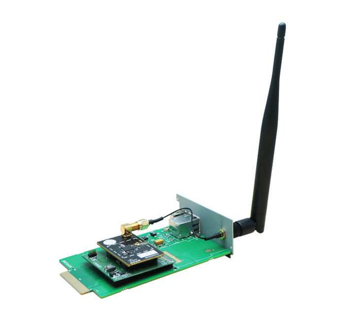
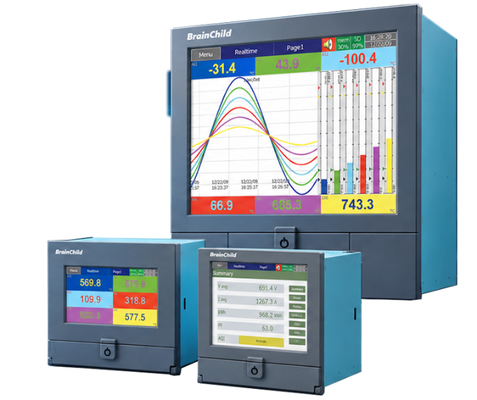
Wireless Expansion Module for PR Paperless Recorders

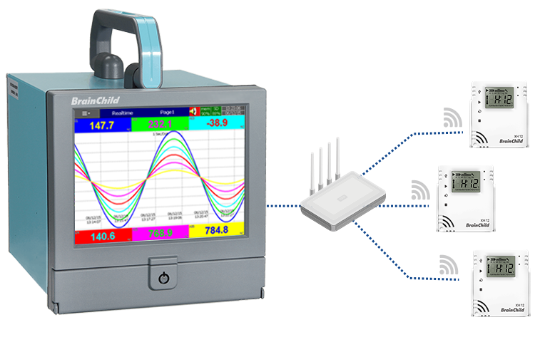
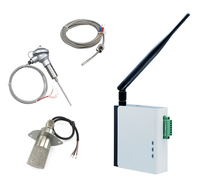
PR Mesh works with SenseNode wireless sensor nodes to extend the wireless measurement capabilities of existing PR Paperless Recorders.

Features


Wireless  Measurement Expansion

Extend the wireless measurement capabilities of existing PR Paperless Recorders with PR Mesh, without replacing the entire recording system.

Distributed Signal Acquisition

Deploy SensNode near measurement points to acquire up to two analog inputs per unit, reducing long-distance sensor wiring to the recorder.

BrainChild Mesh
Connectivity

Powered by BrainChild Mesh wireless technology, SensNode transmits field measurement data to PR Mesh, connecting distributed measurement points with the PR recorder.

Seamless PR Integration

Installed inside a compatible PR recorder, PR Mesh integrates wireless measurement data into the existing system while preserving its familiar interface and operation.

Centralized Monitoring & Recording

Consolidate measurement data from distributed points in the PR recorder, retaining real-time displays, trend monitoring, alarm management, and historical data logging.

Scalable Monitoring Expansion

Add SensNode units as monitoring needs grow, extending measurement coverage while reducing wiring and installation work when expanding existing systems.


​  

How it work

Extend Your PR with Flexible Wireless Measuremen


➊ Field Signal Acquisition 

SenseNode acquires sensor signals near measurement points and wirelessly transmits the data using BrainChild Mesh technology.

➋ Wireless Data Reception & Integration

PR Mesh receives measurement data from SenseNode and integrates it into the existing PR recording system.

➌ Centralized Monitoring & Data Logging

The PR recorder provides centralized access to real-time measurements, historical trends, alarm information, and data logging.

Less Wiring. Greater Flexibility.

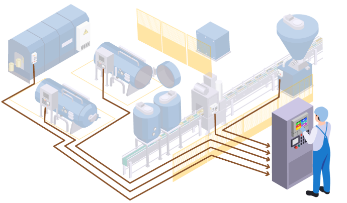
Traditional Wired Monitoring


Traditional wired monitoring systems require sensor signals to be connected directly to centralized recording equipment. When measurement points are widely distributed, located far from the recorder, or added to existing production lines, additional wiring and installation work can make system expansion and maintenance more complex.

Traditional Wired Monitoring


Traditional wired monitoring systems require sensor signals to be connected directly to centralized recording equipment. When measurement points are widely distributed, located far from the recorder, or added to existing production lines, additional wiring and installation work can make system expansion and maintenance more complex.

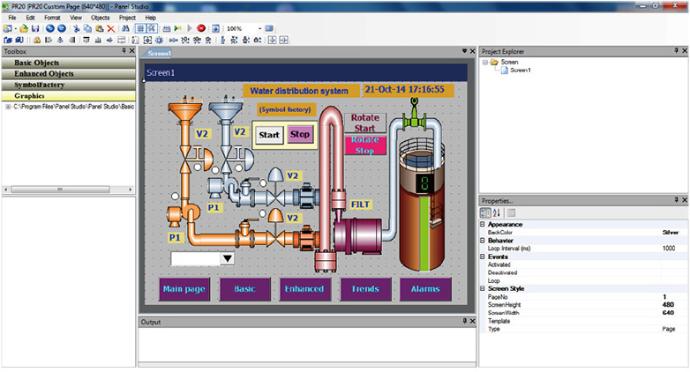
IV. Panel Studio

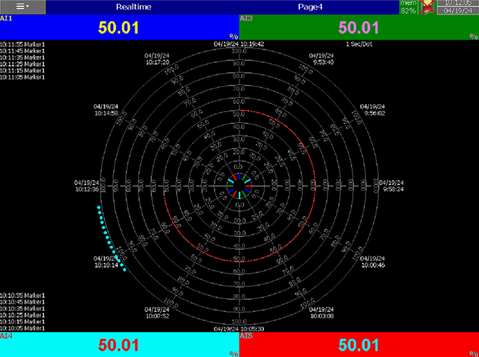
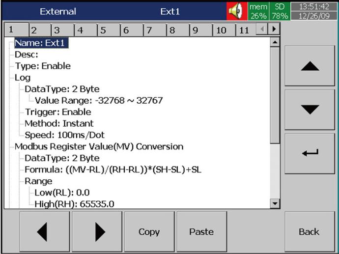
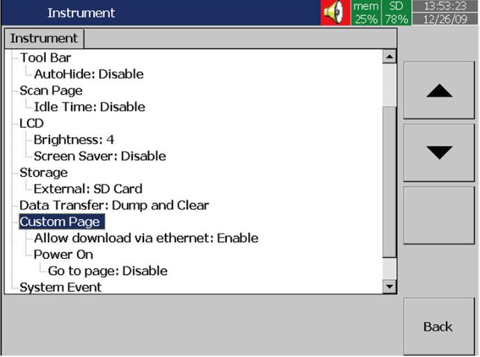
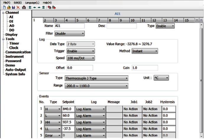
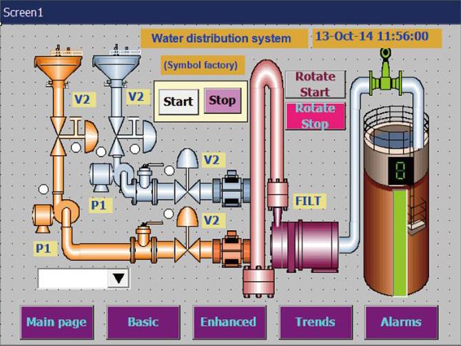
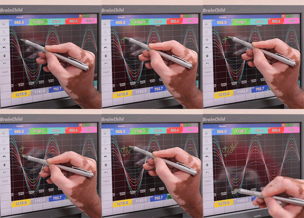
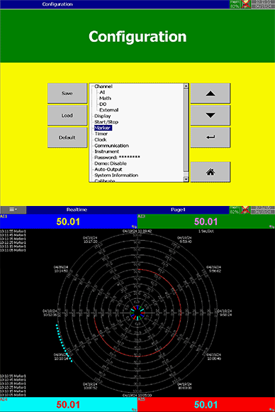
If Plus version 2 or 3 of Firmware is purchased, additional software Panel Studio is offered for editing custom display. The users can use it to edit specific displays on PC first, and then download it onto recorders. The custom edited displays will be additional pages to standard ones.

Edit it on PC 

Download it onto Recorders 

Applications

Specification


Product position

Big size and high-end one, good for sophisticated applications, for example power industry

Input numbers

6, 12, 18, 24, 30, 36, 42, 48 channels

True universal inputs

Thermocouples: J, K, T, E, B, R, S, N, L, U, P, W5, W3, LR, A1, A2, A3, M
RTD: Pt50, Pt100, Pt200, Pt500, Pt1000 (α=0.00385), Pt50, Pt100 (α=0.00391), Ni100, Ni200, Ni500,JPt50, JPt100, JPt200, JPt500, JPt1000 (α=0.003916) Ni1000 (α=0.00617) mA, V, mV

The fastest sampling rate

o reach 100 msec / dot, default setting at 1 sec / dot

Math, External channels, Batch,
Custom display, FDA 21 CFR part 11

Math in standard version, others in Plus versions

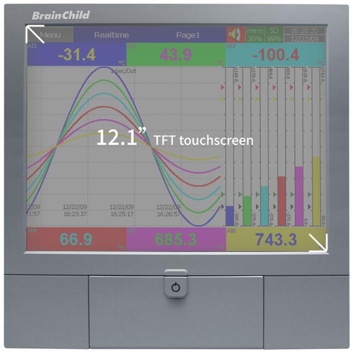
Display

12.1" TFT touch screen

Resolution

1024 x 768

MTBF backlight at 25°C

30,000 hrs

Backlight

LED

Screen saver, Email

Yes

A faster CPU

ARM Cortex-A8, 1Ghz

Internal flash memory

256 MB

RAM

256 MB

Ethernet

Modbus TCP/IP

RS-232/422/485

Optional RS-232 or RS-422/485 Modbus RTU

SD card slot, USB host x 2

Standard, one USB in the front, another USB in the back

Pulse input

Optional DI card offering either logic or high frequency pulse counter

START / STOP key

To start / stop record and to turn off the display only, not recorder itself so that a quick start possible

Calibration correction

On-site calibration possible, or using handy features of Offset and Gain for correction

Multilingual

Convenient for local users by offering 19 languages including English, Japanese,Danish, Italian, Polish, Russian, Dutch, Korean, Thai, Turkish, Portuguese, Chinese(simplied, traditional), French, German, Spanish, Swedish, Brazil Portuguese, Czech, other languages negotiable

PC software Historical Viewer+ Configuration

Standard

Extensive software Data Acquisition Studio

Optional real-time monitoring

Power supply

90-250VAC or 11-36VDC

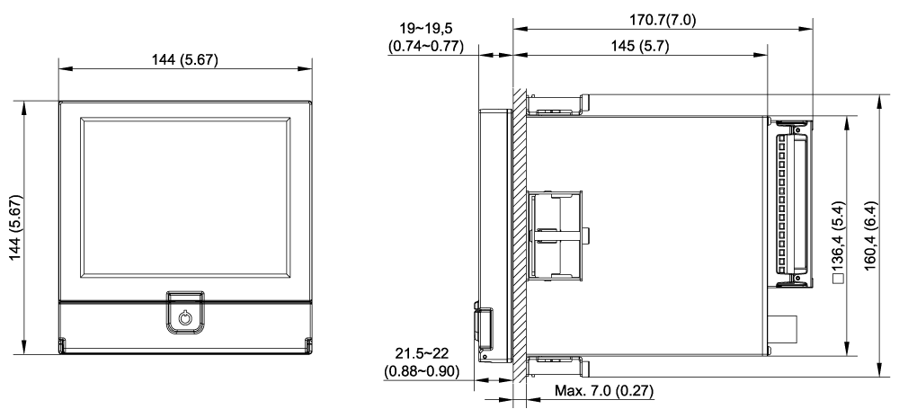
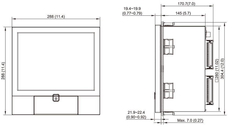
Outer dimensions (W x H x L mm)

288 x 288 x 189

Shorter mounting depth (mm)

171

DIN panel cutout (W x H mm)

 281 x 281

Protection

IP65 front, IP20 rear

Operating temperature

0°C to 50°C

Storage temperature

-30°C to 70°C

Safety standards

RoHS

Download

Visit Download Center to See More Documents & Tools of This Product.     Visit

FAQ

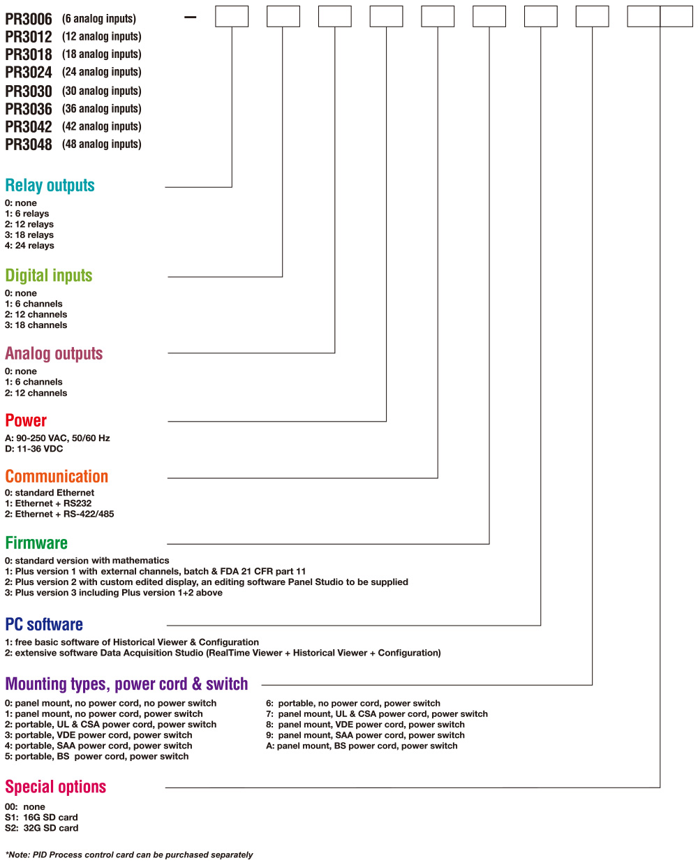
Ordering Code

PR3006(6 analog inputs)
PR3012(12 analog inputs)
PR3018(18 analog inputs)
PR3024(24 analog inputs)
PR3030(30 analog inputs)
PR3036(36 analog inputs)
PR3042(42 analog inputs)
PR3048(48 analog inputs)
none
6 relays
12 relays
18 relays
24 relays
Digital inputs
6 channels
12 channels
18 channels
none
6 channels
12 channels
90-25 VAC,50/60 Hz
11-36 VDC
12 channels
standard Ethernet
Ethernet + RS232
Ethernet + RS-422/486
standard version with mathematics
Plus version 1 with external channels, batch & FDA 21 CFR part 11
Plus version 2 with custom edited display, an editing software Panel Studio to be supplied
Plus version 3 including Plus version 1 +2 above
standard version with mathematics
Plus version 1 with external channels, batch & FDA 21 CFR part 11
Plus version 2 with custom edited display, an editing software Panel Studio to be supplied
Plus version 3 including Plus version 1 +2 above
free basic software of Historical Viewer & Configuration
extensive software Data Acquisition Studio (RealTime Viewer + Historical Viewer + Configuration)
panel mount, no power cord, no power switch
panel mount, no power cord, power switch
portable, UL & CSA power cord, power switch
portable, VDE power cord, power switch
portable, SAA power cord, power switch
portable, BS power cord, power switch
portable, no power cord, power switch
panel mount, UL & CSA power cord, power switch
panel mount, VDE power cord, power switch
panel mount, SAA power cord, power switch
panel mount, BS power cord, power switch
Protected by reCAPTCHA, Privacy Policy & Terms of Service apply.
將其替換為您自己的 HTML 代碼